I’m in the process of replacing a windmill on the farm with a solar pump. The windmill, carefully adjusted, can keep up with the water consumption at the house and troughs a couple of kilometers away. It isn’t perfect; sometimes the house tank overflows and we either water the garden or go down and turn the windmill off for a few days. Sometimes the tank sounds a bit empty and I drive down to the windmill and adjust it for a bit more flow.
The solar pump is not so analogue. In order to lift the water the height needed, the centrifugal pump is oversized in relation to the actual flow required. The pump controller can be turned down to some extent, not not enough to avoid overflowing the tank and wasting water. Some system is needed to turn it off an on remotely. My current plan for this is to use DTMF tones over UHF CB radio.
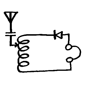
 Dual-tone multi-frequency signalling (DTMF) tones are used widely in telephone systems. The frequencies are chosen to be easily transmitted in the narrow voice bandwidths and using two tones for each key allows for a small amount of frequency drift as well as good rejection of noise.
The frequencies were originally chosen far enough apart to use analogue bandpass filters for detection, so it’s possible that someone smarter than me could implement a simplified Fourier transform that would run on the Arduino. As I need this to be robust, I rejected that idea and decided to use an MT8870 Integrated DTMF Receiver.
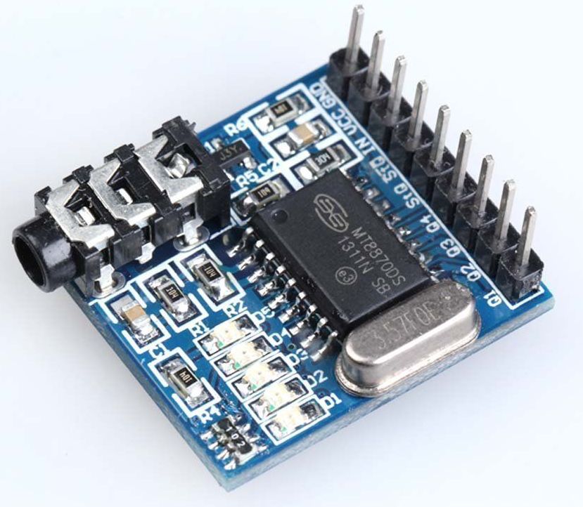 With a handful of supporting components, this chip will apply filters and digital counting to the incoming analogue signal and output the information as full rail states on five pins. To save money, time, and effort, I purchased a pre-built module for $3.86 on ebay. A particually nice feature of this module is that it has status LED’s for each of the output pins – a real bonus when I was debugging my code.
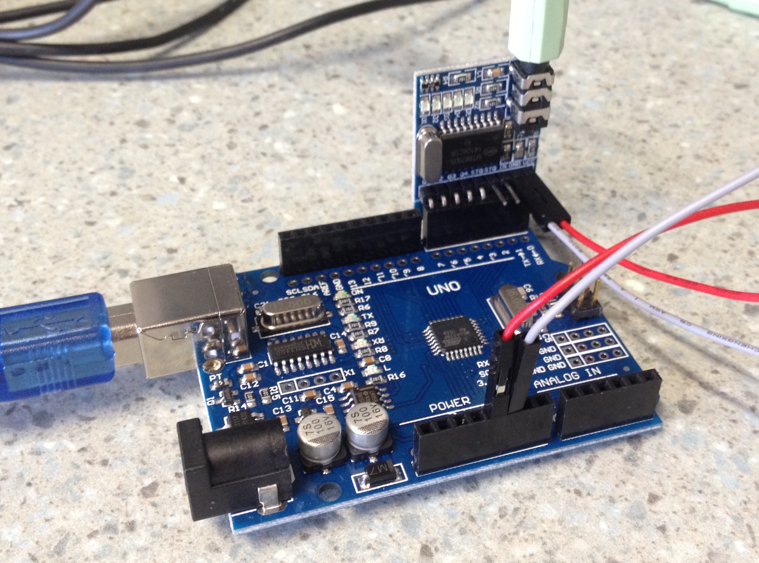 It was straightforward to wire up – just the power supply, ground and the five output pins to the Arduino Uno inputs. Arduino users will note I’ve changed to the cheap Chinese Arduino clones. At around $5.00 they are great value, but one of the reasons they are so cheap is that they do not use the common FDTI chip for serial comms over USB. Instead they have one of the CH34x chips. These seem to be functionally equivalent, but you’ll need to track down and install the driver. I didn’t have any drama with this (Mac) but I see many people have been. If you want to avoid all that, just but the genuine ones ($12 if you can wait for them to come from Asia, $35 otherwise).
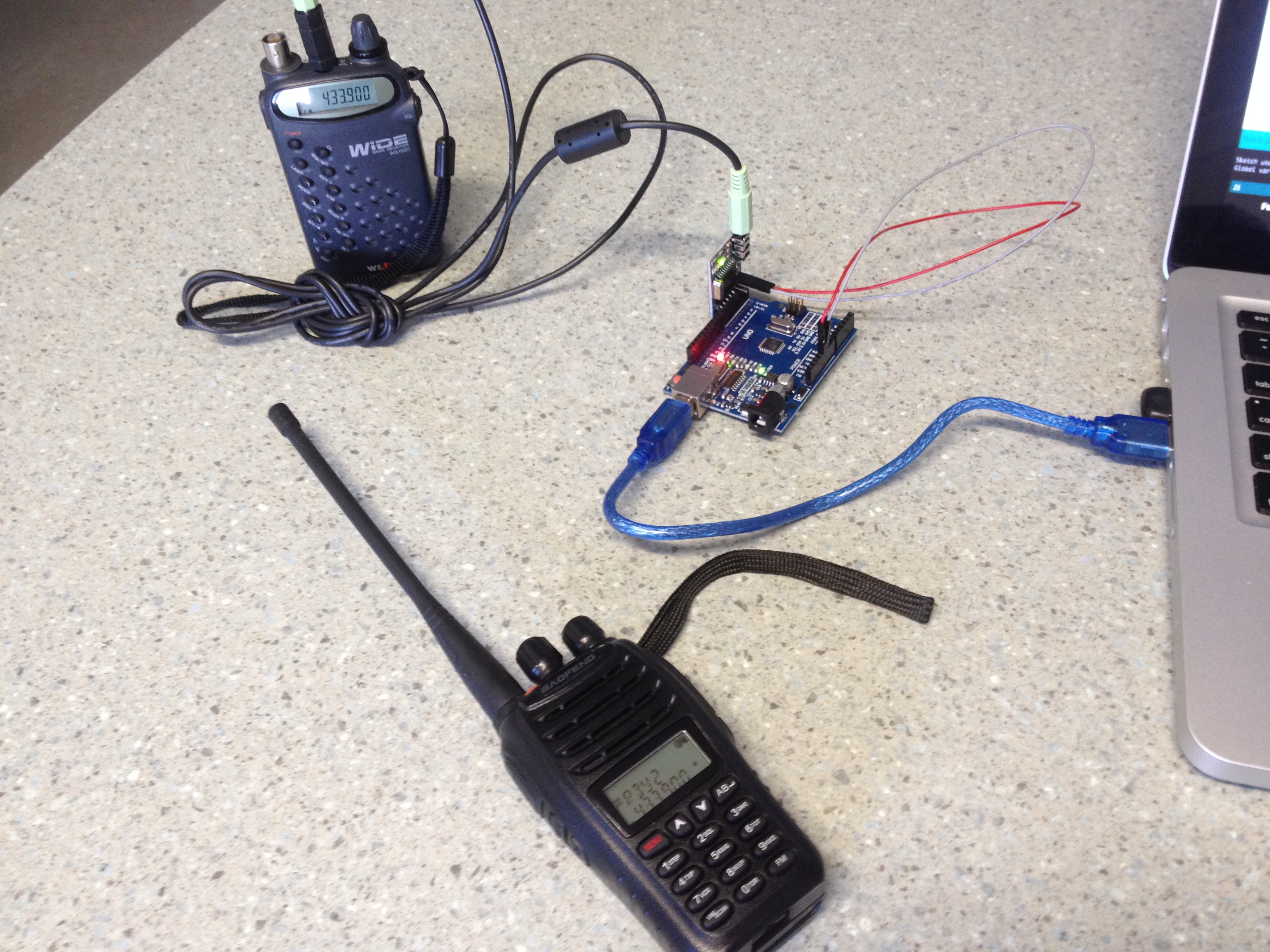 My test setup was a scanner plugged into the module attached to the Arduino, with the Arduino plugged into my USB port, this provided power, serial output for debugging and a source of radio interference! Even without the power supply attached to the laptop, enough RF was getting through to open the squelch on the scanner.
One of the outputs of the MT8870 is a pin which goes high when tones are being detected. The test code I’ve written scans for this, then when it’s detected reads the other pins to determine which code is being received. At the moment, this is just being output as a debug string. When my relay arrives I’ll build up the finished hardware and adapt the code to switch it.
/* ==============================================================================
         Project: MT8870 DTMF Module test
          Author: Ian Bailey VK6MIB
         Created: 19 Jan 2016
     Arduino IDE: 1.6.4
         Website: vk6mib.com
     Description: This little module contains the crystal and everything needed to
                  make the MT8870 chip happy. The chip decodes any detected DTMF
                  tones coming in at audio level and sets a binary code on the
                  Q1-Q4 pins. The STQ pin is low when there is no tone and goes
                  high when a valid tone is decoded. The Q pin state is preserved
                  when the tone stops and STQ is grounded.
  Some credit to: http://arduinobasics.blogspot.com.au/2015/08/mt8870-dtmf-dual-tone-multi-frequency.html
================================================================================= */
//Global variables---------------------------------------------------------------

const int STQ = 3;       // Attach DTMF Module STQ Pin to Arduino Digital Pin 3
const int Q4 = 4;        // Attach DTMF Module Q4  Pin to Arduino Digital Pin 4
const int Q3 = 5;        // Attach DTMF Module Q3  Pin to Arduino Digital Pin 5
const int Q2 = 6;        // Attach DTMF Module Q2  Pin to Arduino Digital Pin 6
const int Q1 = 7;        // Attach DTMF Module Q1  Pin to Arduino Digital Pin 7

byte BoardState;          // current mode/state
const byte WAITING = 0;
const byte START_OF_TONE = 1;
const byte DURING_TONE = 2;
const byte END_OF_TONE = 2;

byte DTMFread;            // The DTMFread variable will be used to interpret the output of the DTMF module.

/*===============================================================================
setup() : Prepare the Arduino to receive the MT8700 DTMF module's output.
============================================================================== */
void setup() {

  //Setup the INPUT pins on the Arduino
  pinMode(STQ, INPUT);
  pinMode(Q4, INPUT);
  pinMode(Q3, INPUT);
  pinMode(Q2, INPUT);
  pinMode(Q1, INPUT);

  // our starting state is waiting for a tone - note this will ignore the first tone
 // if it's being received at boot
  BoardState = WAITING;

  // debug code
  Serial.begin(9600);           // set up Serial library at 9600 bps
  Serial.println("Hello world!");

}

/*===========================================================
loop() : Arduino will interpret the DTMF module output
============================================================ */
void loop() {

  // use the STQ pin to determine what is happening
  byte StqState = digitalRead(STQ);

  if((StqState==HIGH)&&(BoardState==WAITING)){
    BoardState = START_OF_TONE;
    Serial.println("Start");
    DTMFread=0;
    if(digitalRead(Q1)==HIGH){
      DTMFread=DTMFread+1;
    }
    if(digitalRead(Q2)==HIGH){
      DTMFread=DTMFread+2;
    }
    if(digitalRead(Q3)==HIGH){
      DTMFread=DTMFread+4;
    }
    if(digitalRead(Q4)==HIGH){
      DTMFread=DTMFread+8;
    }
    Serial.println(DTMFread);
    BoardState = DURING_TONE;
  }

  if((StqState==LOW)&&(BoardState==DURING_TONE)){
    // the pin has just gone low at the end of the tone, we can reset the state
    Serial.println("End of tone");
    BoardState = WAITING;
  }


}
Phillips FM320 – vk6mib
Hi Ian,
I am busy reinventing an Echolink Controller for our club station. I found some ideas in the Web, but none suited our needs. So I caught the task aof building one. First thing to do was decoding DTMF tones. I fiddled around with the MT8870, but gut stuck on the fact that I did not find an easy way to avoid multiple reads of the same tone. Then I found your code sniplet and bingo that was the solution! Many Thanks!
I modified your code a bit to print the keypad values of the DTMF keypad. If you are interested, drop me a line (dd8zx (at )darc.de, replace (at) with @) and I will mail it to you..
73
Georg, DD8ZX
Hey Georg,
Glad it was some help! Good luck with the rest of your project.
Cheers,
Ian
“I’m working with MT8870 to turn on the water pump using cell phone. The circuit works fine but there is small issue. Here are few things about my circuit,
1. The output (Pin. 11) stays latched which helps to hold relay on continuously until it receive another tone. Relay operated by using pin no.11 (Key “”9″” activate the Relay), 13K resistor & 2N3904 transistor.
2. This operation is as per expectation.
3.The pin 10 is connected to +5 VDC and pin 15 left open.
Here is issue:
When I power OFF-ON the circuit within 1-2 minute with activated relay, the relay stays latched but if I power OFF – ON the circuit with 20-30 min time gap the relay stays de-activated.
I don’t want to keep the relay in latch condition even after power OFF-ON cycle with any time gap. The MT8870D output (Pin 11 to Pin 14) should be go low with the power OFF-ON cycle.
Please advice.”